


How to Turbocharge your car

How to Turbo charge your car - Stage 1
Compressor Maps
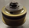
Before embarking on any turbo upgrade or turbo charging a car that is currently atmospheric you must choose the correct Turbo. The non-variable vane turbo is a relatively simple device and consists of inducer and exducer on both hot and cold sides. Energy from the exhaust (mainly in the form of heat) powers the turbine, the shaft then spins the compressor to pressurise intake air. Intake air increases in pressure therefore the engine can flow more air and make more power. The downside is heat is created on the intake side and heat before the turbo is created on the turbine side.
These inefficiencies can lead to failure. Successful turbocharging is all about heat management.
Back to the map. The turbo is happiest operating within a range. This range is defined by the size of the inducer and exducer on both turbine and compressor side and their ratio to each. Then the housing comes into play as well.
If you are starting from scratch though the most important thing is the map. Fortunately there is a very easy ready reckoner for the the sizing. Airflow lb min x 10 = hp. So 35lb min = 350 hp - simples!
That is for Garrett Turbochargers you will find the figures for airflow in lb/min. It isn't quite as simple as this and for that reason I have constructed a spreadsheet to make this lookup much easier.
You simply add the Engine size, RPM, Volumetric efficiency, Compression ratioo, Atmospheric pressure and it gives you the air requirement in lb min. You can then size the turbo to suit the required output range of the engine. It is important to ensure that pressure ratio and airflow do not cause the turbo to operate outside the map as surge or stall will occur. The peak efficiency of the turbo is acheived in the middle of the compressor map - on the GT2560R map above you can see a line with 75% efficiency on it and 110000 rpm. This equates to pressure ratio of 1.75 and airflow of 20lb min - approx 200hp. So this blower is at peak efficiency at this point. Max flow is 35lb min pressure ratio just over 2 and approx 143000 rpm. So if you were building a 250hp-300 hp engine with approx 2 bar absolute boost (1 bar over atmospheric) this is perfect. For a 300hp plus engine at more than 2 bar absolute a better choice would be a GT2871.
These general rules apply - The bigger the capacity the slower the spool and also the bigger the capacity the higher the rpm the engine will make. In fact if you are careful with sizing you can actually improve the high rpm performance of a 2 valve engine.
I remember my old 205 GTi Turbo revving past 7500 with ease with the turbo whereas without it lost verve at 6500rpm.
Unfortunately for most European turbochargers the compressor maps look like this

Their isn't such an easy cross check as the lb min and partly this is because these maps work with cubic metres per second which is volume not weight !
It is pretty easy to see how you can rack and stack your turbos to get the amazing outputs achieved by some engines. Multiple compressor stages keeps heat under control and maximises final boost / flow vs temperature to get maximum horse power.
How to turbo charge your car - Stage 2 - Turbo Location
Should the turbo always be as close to the head as possible?

Conventional wisdom suggest so. Most modern Turbo cars have a log type cast manifold that puts the turbo just a few inches from the head. The logic is you want to maximise the heat energy available for a turbo. A turbo is principally a heat powered device. The compressor maps we looked at last time showed the Adiabatic efficiency of the turbo. If a turbo was a 100% efficient then no heating of the inlet charge would occur. Unfortunately they are not an inevitably heating of the compressed inlet charge does occur and efficiency rarely exceeds 75%.
So is the log type cast manifold the pinnacle of design? Well no. The picture shows the old Brabham BMW F1 engine (the 1400hp from a 1.5litre on funky fuel). It is clear to see the engine has a proper equal length tubular manifold which dictates moving the turbo some distance from the head. The benefit is the exhaust tuning is not sacrificed unlike a log type manifold which rarely optimises exhaust flow. Another benefit of the more "remote" set up is that heat into the head is dramatically reduced. You can see how much hotter the exhaust turbine is than the manifold near the head. This puts less stress on the exhaust valves and associated components. I remember on an 16 Valve Fiat turbo I bought once that the exhaust cam had worn down due to excessive heat and was only opening the valves 4mm!
So if you are building a high power turbo conversion give due consideration to the manifold set up. You could if you want to really break with tradition mount the turbo remotely. You may have seen the "crazy" rear mount turbo I did on the 205 project some years ago. Although it still relies on heat to work some design aspects are changed - the exhaust diameter before the turbo must not be too large and the turbo can be smaller than it might be mounted conventionally. It's not a new idea and the many benefits it brings explain this concepts use on WW2 fighters such as the P47 Thunderbolt.

So the bottom line is if you are seeking big power and going to run the high pressure ratios that entails you may well find the factory log type manifold is not suitable.
How to turbo charge your car - Stage 3 controlling the turbo

So you've decided on the right size turbo and you've worked out where you will locate it - however how will you control it?
A modern turbo car has fine control of the turbocharger. They normally employ either electro-pneumatic or electric control of the wastegate. They have a complicated system of closed loop control which ensures the turbo responds with the throttle - not against it.
You may have driven a turbo car with boost controlled by an aftermarket boost controller. These can be really useful with different maps for different power levels. However it is rare to find one with a Throttle Position Sensor input. Without a TPS input the Turbo can overspeed against the throttle butterfly even at small openings. This is particularly prevalent at higher engine speeds, e.g exit a bend, give a small amount of throttle and "whoosh", loads more boost arrives than you required and you end up snapping the throttle which can sometimes cause stall.
This is why I prefer a full standalone aftermarket ECU (like the Emerald ECU) which gives you the ability to tailor turbo response not just via a closed loop boost map but also via the TPS. This will enable fine control of the turbo to ensure that the pressure ratios vs load sites enable you to control the turbo within the parameters of its compressor map.
Another thing to remember is that if you are boosting an atmospheric engine you may be doing a low pressure install. In which case you may only want 0.2-0.3 bar above atmospheric. Remember then that turbos with built in actuators and wastegates usually have a base boost level of 0.4 bar. In this case you are better off with a separate waste gate allowing control of the turbo boost to very low levels.
Login to post comment
-
 Koni Special Active on a 2023 Audi A4 Avant 2.0 TFSi April 09, 2024
 -
 When should dampers be serviced or replaced? February 14, 2024
 -
 Morris A Series Tune up December 27, 2023
 -

-
 Alfa Giulia 2.0 Veloce supply and fit Ragazzon exhaust September 01, 2023